Remember that we are just pumping refrigerant around. Refrigerant is a special
chemical (usually a complicated petrochemical, though some newer ones are simple molecules
like propane) that is usually a vapour (a gas, in everyday speech) at standard temperature
and pressure, but can easily move between liquid and vapour at the set points we care about.
There are 4 main components of electric heating and cooling that use what’s called the
vapour-compression cycle. We use this cycle because it is, by far, the most
efficient way to move heat around due to a couple of really neat physics tricks. There’s a
load of new “heat” “pumps” getting press, but most of these break down in some way or another.
Vapour compression is the workhorse.
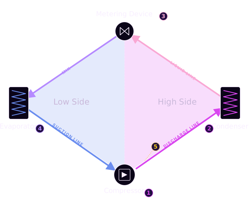
The four components, arranged around a low-side / high-side divide. The dashed
5 marks where the reversing valve sits on a heat pump.
It swaps the discharge and suction routing so the outdoor coil and indoor coil trade roles
between cooling and heating mode.
The four (well, five) main components, in order
1. Compressor. Takes in cold, low-pressure refrigerant vapour and outputs hot,
high-pressure refrigerant vapour. That’s literally what it does. Compress things. It also serves
as the pump that moves the refrigerant through the system.
This is the largest energy user in your heat pump. Everything else is mostly
passive. The compressor is the only place electricity gets converted into useful work in the
cycle.
2. Condenser. The equivalent of the radiator at the front of a car with fans
sucking in air across it. The hot, high-pressure vapour coming out of the compressor flows through
the condenser coils, transfers heat to the air blowing past, and cools just enough that it
condenses from a vapour back into a liquid (hence the name). Importantly, the refrigerant
is still at high pressure here. It’s just cooler. It’s now a hot high-pressure liquid.
3. Expansion valve. A tiny pinhole. On one side, there’s hot liquid refrigerant
at high pressure. On the other side, it’s low pressure. This is where the magic happens.
By squeegeeing the refrigerant through this pinhole, two physics tricks occur simultaneously:
The Joule-Thomson effect. When a real vapour or liquid is forced through a
throttling valve from high pressure to low pressure without exchanging heat with the
surroundings, its temperature changes. The change is described as “isenthalpic,” meaning
enthalpy (the total heat content) stays constant, but temperature drops because the
molecules do work against their own intermolecular forces during expansion. This is why
letting air out of a bicycle tire makes the valve feel cold.
Phase change. As the pressure drops, some of the liquid refrigerant flashes
back to vapour. Phase changes absorb a huge amount of heat (the “latent heat of vaporisation”),
which further cools the refrigerant. This is why the vapour-compression cycle is so efficient:
phase changes move way more energy per kilogram of refrigerant than just temperature changes do.
Net result: a hot high-pressure liquid going in, a cold low-pressure two-phase mixture
(mostly liquid with some vapour) coming out. Neat.
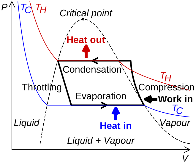
Pressure-enthalpy (P-h) diagram. The horizontal line through the expansion valve is the isenthalpic Joule-Thomson process; the vertical jump at the compressor is where electrical work enters. Diagram by Cmglee, via Wikimedia Commons, licensed under CC BY-SA 3.0.
4. Evaporator. Looks like a car radiator, but works in reverse. The cold
refrigerant from the expansion valve runs through the evaporator, picks up heat from the room
air (in cooling mode) or from the outdoor air (in heating mode), and boils back into a
vapour. Then back to the compressor inlet to do it all over again.
5. Reversing valve (the heat pump special). In a heat pump (as opposed to a
one-way air conditioner), there’s a fifth component: an electrically-controlled reversing
valve. This valve swaps which physical coil acts as the condenser and which acts as the
evaporator. The coil names refer to function, not location. This is the entire
trick that makes a heat pump a heat pump.
Why is this so efficient?
A traditional electric resistance heater takes 1 kWh of electricity and produces 1 kWh of
heat. Coefficient of Performance (COP) = 1.0. You cannot do better than 1.0 with resistance
heating because the laws of physics forbid it.
A heat pump takes 1 kWh of electricity to move much more than 1 kWh of heat
from outside to inside. Modern cold-climate heat pumps run COPs of 3.0-4.0 in mild conditions,
and still around 2.0-2.5 at 5°F outdoor temperature. You’re not creating heat from electricity.
You’re using the electricity to run a compressor that pumps a refrigerant around a loop, and
the heat is already out there in the outdoor air, free. You’re just relocating it.
SEER2, HSPF2, and the spec sheet alphabet soup
When you actually shop, you won’t see COP on the EnergyGuide label. You’ll see
SEER2 (cooling) and HSPF2 (heating). One-paragraph translation:
SEER2 stands for Seasonal Energy Efficiency Ratio 2. It’s the heat-pump equivalent of MPG:
total BTU of cooling delivered over the season, divided by total watt-hours of electricity
consumed. Higher is better. HSPF2 (Heating Seasonal Performance Factor 2) is the same idea for
heating. Both numbers got the “2” suffix in January 2023, when the U.S. Department of Energy
switched to a harder test (Appendix M1) that simulates real-world ductwork resistance.
SEER2 numbers are 4-5% lower than the equivalent old SEER number on the same equipment. A 15.0 SEER unit roughly equals a 14.3 SEER2 unit.
Federal minimum since Jan 1, 2023: 14.3 SEER2 and 7.5 HSPF2 for split-system heat pumps nationwide.
High-efficiency threshold: 17 SEER2 and above. Top-tier residential units reach 22+ SEER2.
COP vs SEER2: COP is a single-point efficiency. SEER2 / HSPF2 are seasonal averages. SEER2 is more useful for predicting your bill; COP is more useful for understanding the physics.
What to actually aim for. The federal floor (14.3 SEER2 / 7.5 HSPF2) is the bare minimum any new split system will hit. A solid modern install lands at 16-18 SEER2 and 8.5-9.5 HSPF2. Top-tier cold-climate equipment reaches 22+ SEER2 and 10+ HSPF2. Higher is always better in this category, the same number on the sticker means the same number in real life. Bigger numbers, smaller bills.